PROJECT 1 OVERVIEW:
I created the parametric 3d model of "Dynamic Tower" in Dubai using mass modeling interface in Revit. My model could be modified by these parameters:
1- Total Height
2- Floor Heights
3- Floor Rotations
4- Exterior Windows Frame Thickness
I had the following limitation in the modeling process:
1- Floors had to be added manually
2- No random rotation pattern
3- Floors were not scalable
4- No connection between different categories
(Height and Frame thickness)
To overcome these limitation I had to remodel my family mass and also use Dynamo which is a Revit plugin.
REMODELING THE FAMILY MASS:
I started the final project by remodeling the family mass of the floors to make them scalable. The previous model was created from various lines and curves and scaling the mass using one parameter was impossible. I created the new family using points that define the edges and have a certain distance from the center which can be changed by one parameter. These points are connected using "Spline through points" function to create a closed boundary.

I defined new parameters to change the shape of the wings by the defined factors of F1 and F2 which will be multiplied by the main radius. I made F1 and F2 as instance parameters so I can change them for each floor individually.
DYNAMO:
I used Dynamo which is a visual programming application to create my parametric tower.
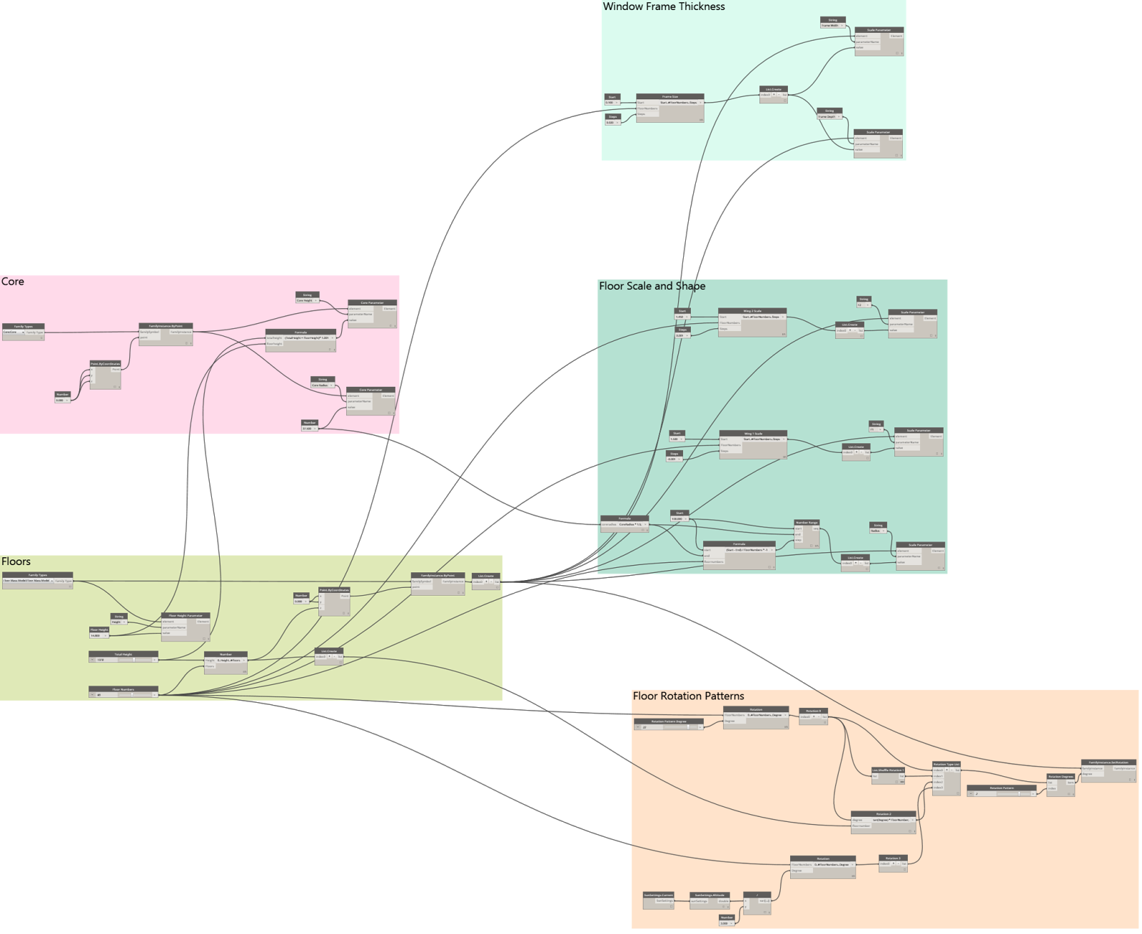

I categorized the nodes into 5 groups so it can be read easier. The two groups on the left create the main elements of the building and the three on the right are making modifications to the model based on the implemented family instances.
FLOORS:

In order to place the family instances and create the tower I used "Family Instances By Point" node. I used number nodes to define the total height and number of points which will be defined as the number of floors. So I created a list of numbers from 0 to "Total Height" which defines the Z coordinate in "Point by Coordinates" node. By connecting my "Floor Mass" family type and points to the "Family Instances By Point" node I created the tower. So by changing the range of the total height I could make the building taller or shorter. Also I can change the number of points (number of Z coordinates in the list) and get different number of families which means different number of floors.
- Changing the "Total Height" node from 1378 to 2000:


- Changing the "Floor Numbers" node from 80 to 40:


I defined another node to change all of the floors' heights at the same time using the "Set Parameter By Name" node.
- Changing the "Floor Height" node from 14.8 to 10:

CORE:

I created a cylinder mass and loaded the family into my model. Using "Set Parameter By Name" node I could change the radius and height of the cylinder. I related the height of the cylinder to the total height by a formula so the cylinder height will be always slightly higher than the total height.
The radius of the cylinder will define the minimum radius of the top floor of the building on the subsequent nodes so it will be always bigger than the cylinder radius. It means by changing the cylinder radius the shape of the tower will change.
- Changing the radius "Number" node from 37.5 to 25:


FLOOR ROTATION PATTERNS:

I used the "Family Instances Set Rotation" node to rotate the floors. I used the list that I created for floor numbers to give each floor a different rotation. I created 4 different rotation patterns. I connected all of the rotation lists to a single list so I can choose each pattern by changing the index number:
0- This pattern creates rotations for floors based on their floor number. The number node will give different degrees to the pattern.
- Changing "Rotation Pattern Degree" from 0 to 3:


1- I used "List Shuffle" node to create random rotation pattern for my model.
- Random rotation pattern:

2- In order to create an irregular interesting rotation pattern I created a formula based on the tan(degree) and floor numbers.
- Formalized rotation pattern based on tan(22):
3- I used the "Sun Setting" node to get the "Sun Altitude" so I can get different inputs for my rotation pattern's simple formula based on the sun position.
- Changing the sun position from 10:00 AM to 7:00 AM:


FLOOR SCALE AND SHAPE:

I used "Set Parameter By Name" nodes to change the radius of floors, F1 factor and F2 factor (which modifies the wings edges) based on the floor number. So the main radius or edge radius will increase or decrease gradually.
- Changing the base floor's radius "Number" node from 100 to 150:


- Changing the center edge (F1) radius steps "Number" node from -0.001 to +0.002:

- Changing side edges (F2) radius steps "Number" node from +0.001 to +0.005:

Window Frame Thickness:

I used the "Set Parameter By Name" nodes and connected them to the number of floors so the thickness of the windows will increase or decrease based on the defined start and steps.
- Changing the steps "Number" node from 0 to 0.02:

Animation:
